# Raspberry Pi Extension Board
A custom PLC-like system based on the Raspberry Pi.
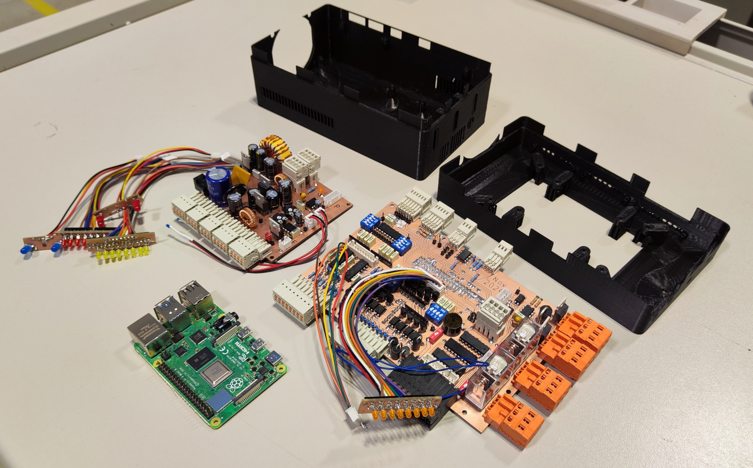
With a custom interface board, a Raspberry Pi is extended with protected I/O, bus systems, analog inputs, and Relay or PWM outputs. All components, including a display, are housed in a custom-designed enclosure.
The project is intended for versatile use in prototyping and project development.
---
## Photo of All Hardware Components
---
# Repository Content
- **KiCad Projects**: 3 KiCad projects with schematics and PCB layouts for the custom PCBs created.
- **Housing**: Custom enclosure design for PCBs and Raspberry Pi created in FreeCAD.
- **Software/Firmware**: Python scripts run on the Raspberry Pi for operating and testing the PCB features and providing examples as base for future projects.
---
# Features Overview
This project provides:
- Protected GPIO I/O for Raspberry Pi.
- Various analog inputs.
- Flexible power supply options (3.3 V, 5 V, -5 V, 12 V, 24 V outputs).
- Relay and MOSFET control.
- Integrated LEDs for status indication.
- RS485, I2C, SPI, and UART bus communication.
Detailed features of each PCB are described in the respective sections below.
---
# Designed PCBs
## 1. Raspberry Pi Interface Board
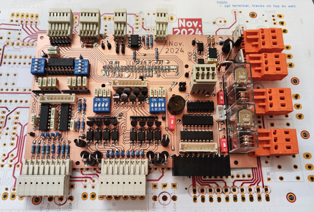
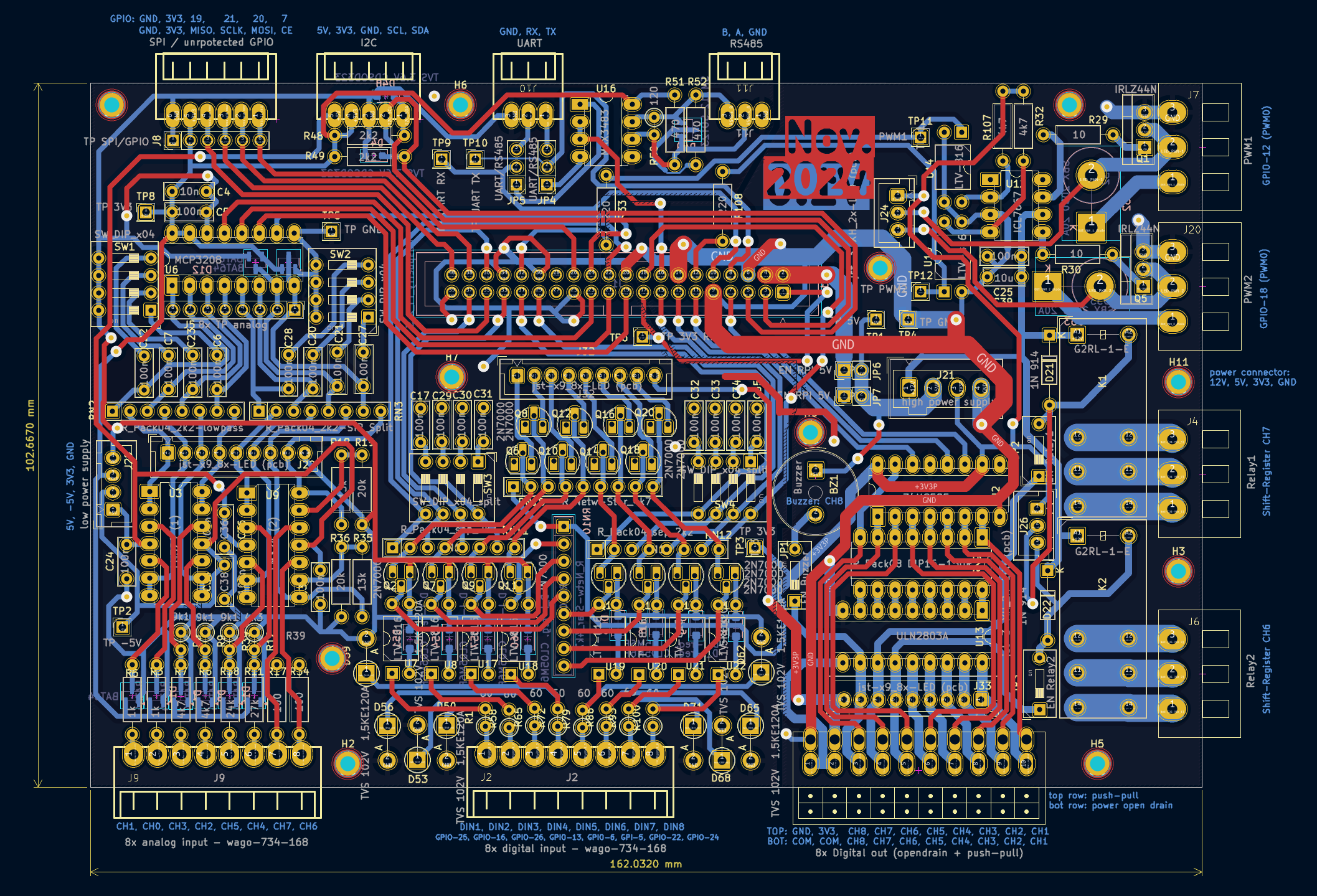
This board connects to the Raspberry Pi via a 40-pin ribbon cable and provides protected GPIO extensions and versatile input/output features.
### Photo
 ### Features
**Inputs**:
- **8x Digital Inputs**:
- Wide voltage range (-1.7 V to 120 V) → compatible with 3 V and 24 V devices.
- TVS diodes for ESD and spike protection.
- Reverse polarity protection.
- Isolated with optocouplers.
- Optional low-pass filters (toggle via DIP switches).
- **8x Analog Inputs**:
- Different fixed range inputs:
- 2x 0 - 3.3 V.
- 2x 0 - 5 V.
- 1x 0 - 12 V.
- 1x 0 - 24 V.
- 2x 0 - 20 mA.
- Overvoltage protection with clamping diodes.
- Optional low-pass filters (toggle via DIP switches).
**Outputs**:
- 1x onboard buzzer.
- 2x 16 A relays.
- 2x high-power MOSFETs (N-channel, max 55 V, 33 A continuous, 160 A pulsed).
- 8x digital outputs (via shift register):
- Low-power (30 mA push-pull) and high-power (500 mA open-drain) outputs.
- Buzzer and relays connected to channels 6-8, with enable/disable switches.
- **Note**: Outputs are **not short-circuit proof**.
**General**:
- WAGO spring-loaded terminals for easy wiring.
- JST connectors for external LEDs for all inputs and outputs to indicate the current pin state.
**Bus Communication**:
- RS485 (TVS protection, idle pull-up/pull-down, 120 Ω terminator).
- UART (unprotected).
- I2C (TVS diodes, 2.2 kΩ pull-ups).
- SPI (unprotected).
- **Note**: RS485 and UART cannot be used simultaneously (select via jumpers).
### Schematic and Layout

---
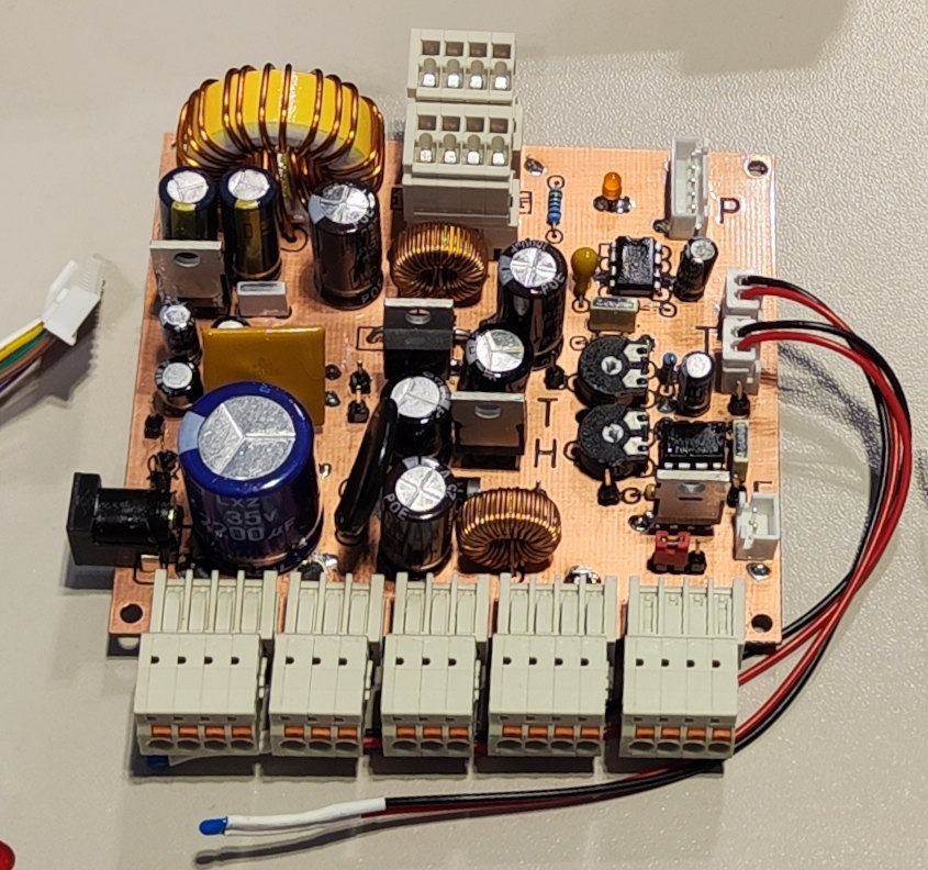
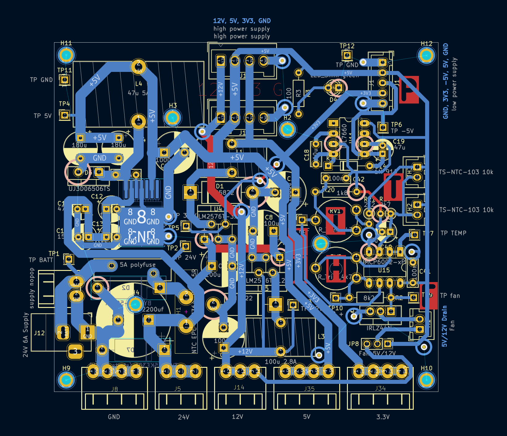
## 2. **Power Supply Board**
Creates different voltages from supplied 24 V. Supply for the Raspberry Pi interface board as well as several terminals for variable use (connect sensors, devices, etc., to the housing).
### Photo
 ### Features
**Input**:
- 24 V 5 A barrel plug.
- 5 A self-resetting polyfuse.
- Reverse polarity protection.
**Output**:
- 3.3 V, 3 A (buck converter).
- 5 V, 5 A (buck converter).
- -5 V, 20 mA (charge pump).
- 12 V, 3 A (buck converter).
- 24 V (supply voltage filtered).
**Fan Control**:
- 2x connector for 10 kΩ NTC.
- Threshold adjustable (trimmer potentiometer).
- Hysteresis adjustable (trimmer potentiometer).
- Select between 5 V or 12 V fan.
**General**:
- Spring-loaded terminals for each voltage.
- Combined internal terminals for all voltages.
### Schematic and Layout

---
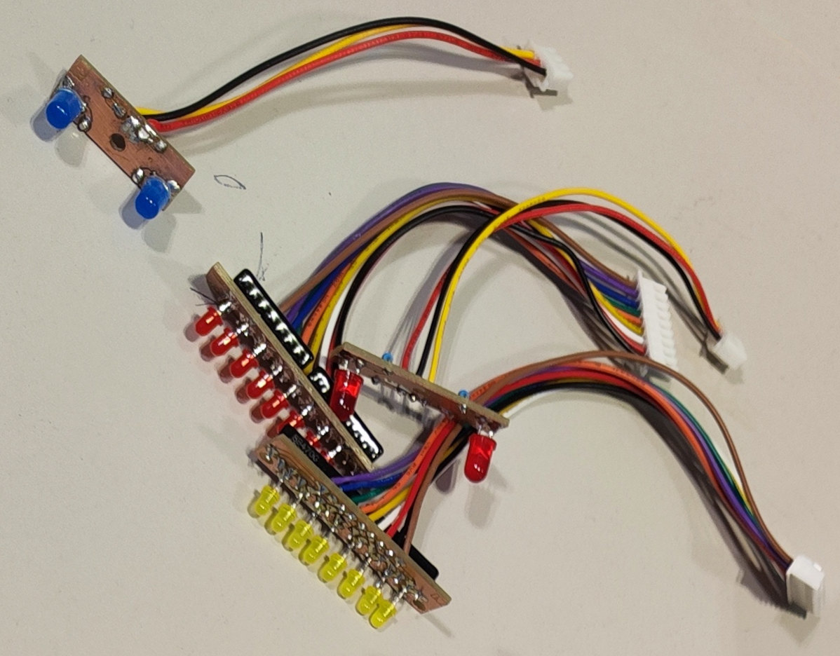
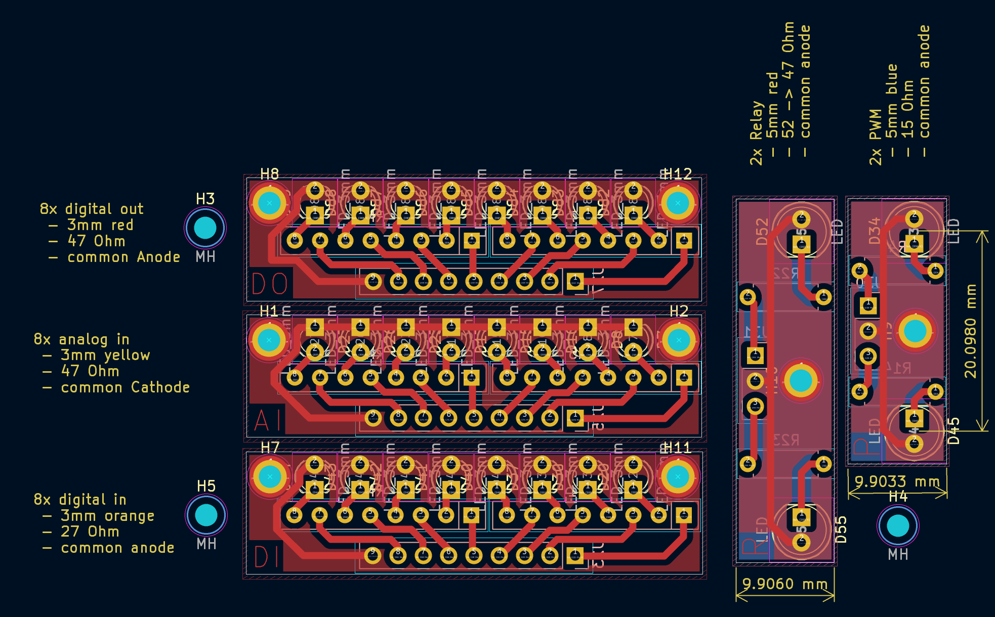
## 3. **LED Boards**
Small PCBs with LEDs, resistors, and mounting holes for housing indicators.
### Photo
 ### Boards
1. 2x 5 mm LEDs for relays.
2. 2x 5 mm LEDs for PWM outputs.
3. 8x 3 mm yellow LEDs for analog inputs.
4. 8x 3 mm orange LEDs for digital inputs.
5. 8x 3 mm red LEDs for digital outputs.
### Schematic and Layout

---
# Raspberry Pi Usage
## Connectivity
The Raspberry Pi can operate **standalone** with a connected keyboard, mouse, and HDMI monitor, or by using the integrated display in the housing.
However, for **development**, it is recommended to connect it to a network via **WiFi or LAN**, allowing easy remote access from a laptop. A direct **Ethernet connection** between the Raspberry Pi and a laptop is often the simplest method.
### LAN Connection (Ethernet)
- **Connection**: Connect cable directly between raspberry and PC
- **Configure the PC interface**: Set a static ip address e.g. `192.168.1.1/24`
Note: Optionally also enable network sharing to enable the RPI to use the internet connection the PC currently has.
- **Configure the Raspberry Interface**: Set a static ip address e.g. `192.168.1.100/24`
The Raspberry Pi can be configured for **Ethernet access** using different methods:
- **Boot Partition Configuration:** Modify `cmdline.txt` on the SD card.
- **GUI Setup:** Use the built-in network manager if a monitor is connected.
- **Command Line (`nmcli`)**: Configure networking via the terminal.
To check the assigned IP run:
```bash
ip a
```
### WiFi Connection
Probably the **fastest and easiest** way to set up communication between the Raspberry Pi and a PC - while even maintaining internet access - is to **use a mobile phone as a WiFi hotspot**.
Simply **connect both the Raspberry Pi and the laptop** to the same hotspot.
To connect to a WiFi network, use:
```bash
nmcli device wifi connect password
```
Replace `` and `` with the actual credentials.
The Raspberry Pi will **automatically reconnect** after a reboot.
Once connected, you can check the assigned IP on the Raspberry Pi using:
```
ip a
```
### SSH Access
For remote terminal access, connect via SSH from a laptop:
```bash
ssh pi@192.168.1.100
```
Replace the IP with the actual address of the Raspberry Pi.
### Remote Desktop (RDP)
To control the Raspberry Pi’s **GUI remotely**, RDP is pre-configured.
#### Connect via Windows Remote Desktop:
- Open **Remote Desktop Connection (mstsc)**.
- Enter the Raspberry Pi’s IP address.
- **Login:**
- **User:** `root`
- **Password:** (configured during setup)
- **Note:** Logging in as `pi` may result in a black screen.
#### Alternatively, use PowerShell:
```powershell
mstsc /v:192.168.1.100:3389
```
### Mount Raspberry Pi Filesystem in Windows (SAMBA)
For convenient file access and editing (e.g., with **VS Code**), the Raspberry Pi’s `/home/pi` directory can be **mounted as a network drive** using Samba.
#### Steps:
1. Determine the Raspberry Pi’s IP address:
```bash
ip a
```
2. Mount the `/home/pi` directory in Windows:
```powershell
net use X: \\192.168.1.100\pi /user:pi
```
Replace `192.168.1.100` with the actual IP address.
**Note:**
Currently, only `/home/pi` is available for mounting. To share additional directories, edit the Samba configuration file:
```bash
# add a new `[share]` section with the desired folder path and permissions.
sudo nano /etc/samba/smb.conf
# then restart samba
sudo systemctl restart smbd
```
---
# Python Scripting
All **terminal-to-pin assignments** are mapped in [`interface_board_pins.py`](rpi-scripts/interface_board_pins.py), allowing easy reference to terminal numbers labeled on the housing.
Example scripts demonstrating I/O control can be found in [`rpi-scripts/examples`](rpi-scripts/examples).
---
## Scripts & Development
### Running Python Examples
Pre-written **Python scripts** to control I/O terminals are located in:
```
rpi-scripts/examples
```
To run an example, execute:
```bash
cd /home/pi/git/rpi-interface-board/rpi-scripts/examples/
python read_digital_inputs.py
```
### Starting a New Python Project with I/O Access
To create a custom Python project using the **interface board**, follow these steps:
1. **Copy the entire `rpi-scripts/` folder** to your new project directory.
2. **Remove unnecessary files**, keeping at least:
- `rpi-scripts/interface_board_libs/` → contains custom drivers.
- `rpi-scripts/interface_board_pins.py` → maps terminal numbers to GPIO/ADC channels.
3. **Start coding** by modifying an existing example in `examples/`.
---
## GUI Interface
A **Python GUI** is available for **real-time monitoring** and **control** of all I/O terminals for quick testing.
### Run the GUI
```bash
cd rpi-scripts/gui
python main.py
```
### Enable GUI Autostart on Boot
The GUI is configured to start automatically on boot in **fullscreen mode**. To modify this behavior:
#### Enable autostart:
```bash
sudo cp rpi-scripts/gui/gui-start.service /etc/systemd/system/
sudo systemctl enable gui-start.service
```
#### Disable autostart:
```bash
sudo systemctl disable gui-start.service
```
### GUI Screenshots


---
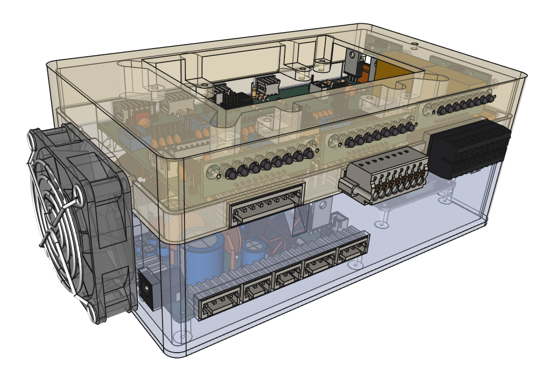
# Housing
Custom-designed enclosure includes:
- Cutouts for all Ports for Raspberry Pi.
- Mounting screws for all pcbs and Raspberry
- Fan mount + venting slots
- Cutouts for all external pcb terminals
- Cutout + mounting arms (M2.5) for Display
 ---
# Dropped Features
The following ideas were considered but not implemented:
- UI Input Elements:
- Buttons, DIP switches, temperature sensors, encoders, or potentiometers.
- USB or battery-powered operation:
- Battery packs with BMS and voltage measurement.
- Li-ion cell holders.
- Analog output (DAC)
- More bus systems
- RS232 Interface
- CAN Interface


 ### Features
**Inputs**:
- **8x Digital Inputs**:
- Wide voltage range (-1.7 V to 120 V) → compatible with 3 V and 24 V devices.
- TVS diodes for ESD and spike protection.
- Reverse polarity protection.
- Isolated with optocouplers.
- Optional low-pass filters (toggle via DIP switches).
- **8x Analog Inputs**:
- Different fixed range inputs:
- 2x 0 - 3.3 V.
- 2x 0 - 5 V.
- 1x 0 - 12 V.
- 1x 0 - 24 V.
- 2x 0 - 20 mA.
- Overvoltage protection with clamping diodes.
- Optional low-pass filters (toggle via DIP switches).
**Outputs**:
- 1x onboard buzzer.
- 2x 16 A relays.
- 2x high-power MOSFETs (N-channel, max 55 V, 33 A continuous, 160 A pulsed).
- 8x digital outputs (via shift register):
- Low-power (30 mA push-pull) and high-power (500 mA open-drain) outputs.
- Buzzer and relays connected to channels 6-8, with enable/disable switches.
- **Note**: Outputs are **not short-circuit proof**.
**General**:
- WAGO spring-loaded terminals for easy wiring.
- JST connectors for external LEDs for all inputs and outputs to indicate the current pin state.
**Bus Communication**:
- RS485 (TVS protection, idle pull-up/pull-down, 120 Ω terminator).
- UART (unprotected).
- I2C (TVS diodes, 2.2 kΩ pull-ups).
- SPI (unprotected).
- **Note**: RS485 and UART cannot be used simultaneously (select via jumpers).
### Schematic and Layout
---
## 2. **Power Supply Board**
Creates different voltages from supplied 24 V. Supply for the Raspberry Pi interface board as well as several terminals for variable use (connect sensors, devices, etc., to the housing).
### Photo
 ### Features
**Input**:
- 24 V 5 A barrel plug.
- 5 A self-resetting polyfuse.
- Reverse polarity protection.
**Output**:
- 3.3 V, 3 A (buck converter).
- 5 V, 5 A (buck converter).
- -5 V, 20 mA (charge pump).
- 12 V, 3 A (buck converter).
- 24 V (supply voltage filtered).
**Fan Control**:
- 2x connector for 10 kΩ NTC.
- Threshold adjustable (trimmer potentiometer).
- Hysteresis adjustable (trimmer potentiometer).
- Select between 5 V or 12 V fan.
**General**:
- Spring-loaded terminals for each voltage.
- Combined internal terminals for all voltages.
### Schematic and Layout
---
## 3. **LED Boards**
Small PCBs with LEDs, resistors, and mounting holes for housing indicators.
### Photo
 ### Boards
1. 2x 5 mm LEDs for relays.
2. 2x 5 mm LEDs for PWM outputs.
3. 8x 3 mm yellow LEDs for analog inputs.
4. 8x 3 mm orange LEDs for digital inputs.
5. 8x 3 mm red LEDs for digital outputs.
### Schematic and Layout


 ---
# Dropped Features
The following ideas were considered but not implemented:
- UI Input Elements:
- Buttons, DIP switches, temperature sensors, encoders, or potentiometers.
- USB or battery-powered operation:
- Battery packs with BMS and voltage measurement.
- Li-ion cell holders.
- Analog output (DAC)
- More bus systems
- RS232 Interface
- CAN Interface