7.3 KiB
Raspberry Pi Extension board
A custom PLC-like system based on the Raspberry Pi.
With a custom interface board, a Raspberry Pi is extended with protected I/O, bus systems, analog inputs, and Relay or PWM outputs. All components, including a display, are housed in a custom-designed enclosure.
The project is intended for versatile use in prototyping and project development.
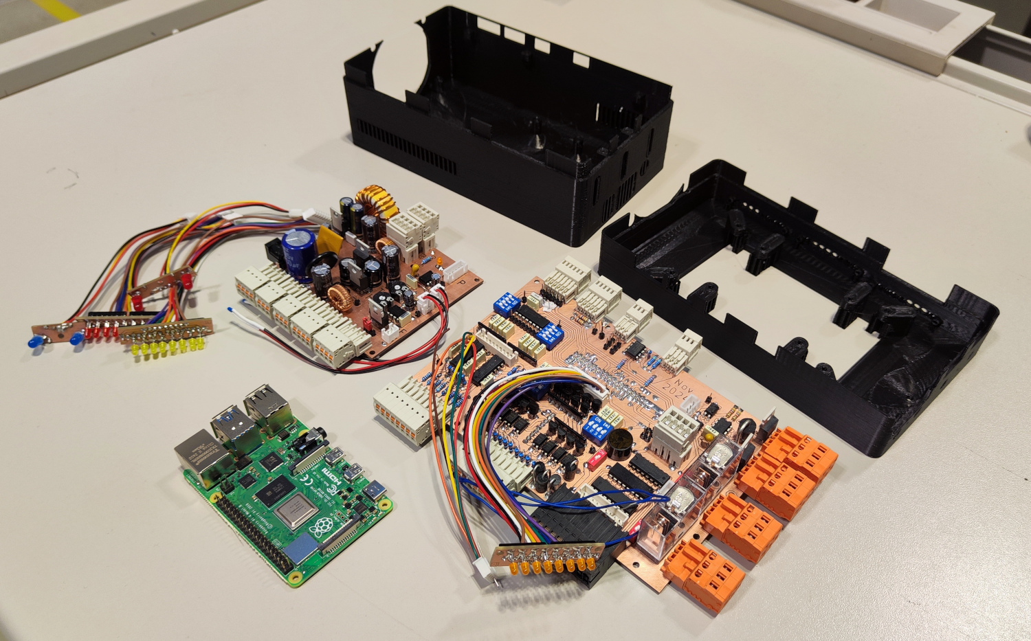
Photo of all hardware components
Repository Content
- KiCad Projects: 3 KiCad projects with schematics and PCB layouts for the custom PCBs created.
- Housing: Custom enclosure design for PCBs and Raspberry Pi created in FreeCAD.
- Software/Firmware: Python scripts for operating and testing the PCB features (WIP).
Features Overview
This project provides:
- Protected GPIO I/O for Raspberry Pi.
- Various analog inputs.
- Flexible power supply options (3.3 V, 5 V, -5 V, 12 V, 24 V outputs).
- Relay and MOSFET control.
- Integrated LEDs for status indication.
- RS485, I2C, SPI, and UART bus communication.
Detailed features of each PCB are described in the respective sections below.
Designed PCBs
1. Raspberry Pi Interface Board
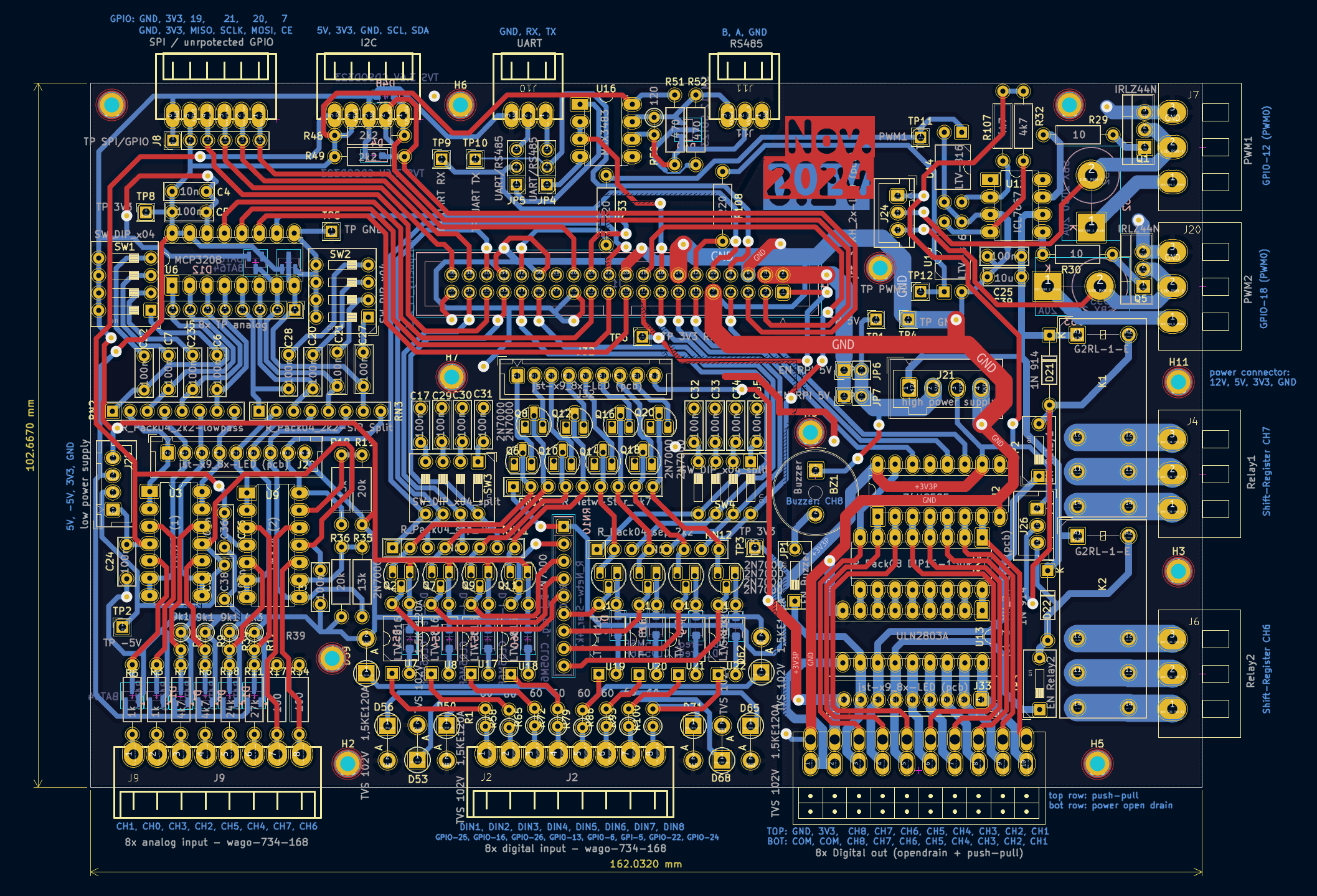
This board connects to the Raspberry Pi via a 40-pin ribbon cable and provides protected GPIO extensions and versatile input/output features.
Photo
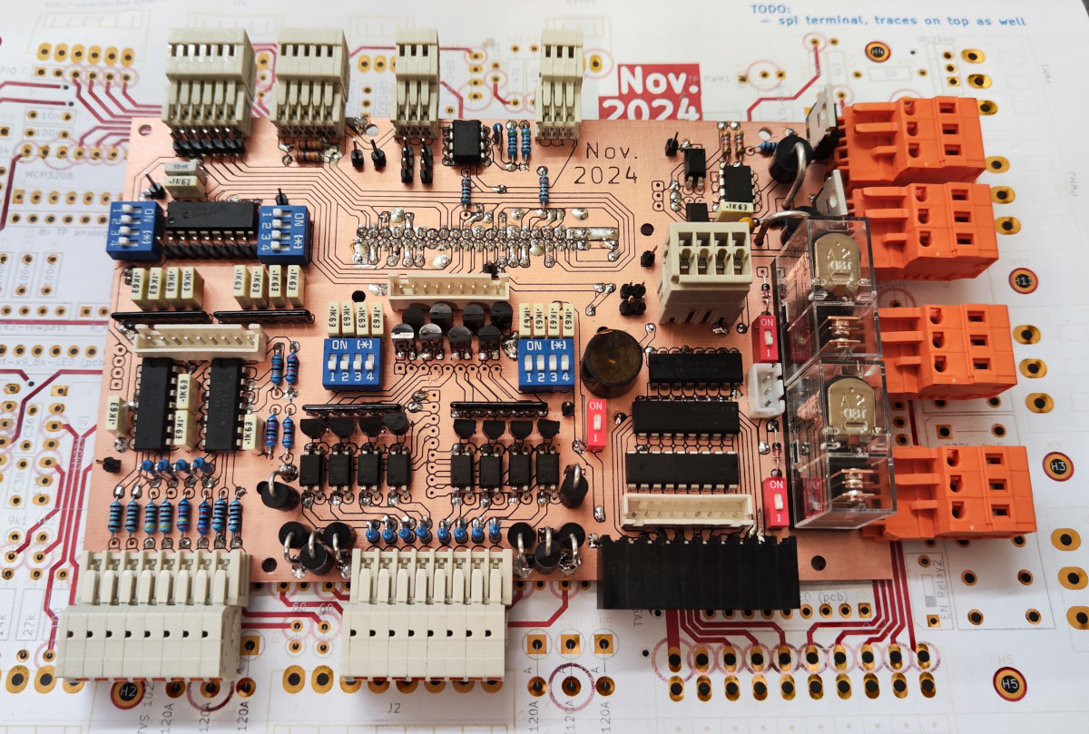
Features
Inputs:
-
8x Digital Inputs:
- Wide continuous voltage range (-1.7 V to 120 V), idea: compatible with 3 V and 24 V devices.
- TVS diodes for ESD and spike protection.
- Reverse polarity protection.
- Isolated with optocouplers.
- Optional low-pass filters (toggle via DIP switches).
-
8x Analog Inputs:
- Different fixed range inputs:
- 2x 0 - 3.3 V.
- 2x 0 - 5 V.
- 1x 0 - 12 V.
- 1x 0 - 24 V.
- 2x 0 - 20 mA.
- Overvoltage protection with clamping diodes.
- Optional low-pass filters (toggle via DIP switches).
- Different fixed range inputs:
Outputs:
- 1x onboard buzzer.
- 2x 16 A relays.
- 2x high-power MOSFETs (N-channel, max 55 V, 33 A continuous, 160 A pulsed).
- 8x digital outputs (via shift register):
- Low-power (30 mA push-pull) and high-power (500 mA open-drain) outputs.
- Buzzer and relays connected to channels 6-8, with enable/disable switches.
- Note: Outputs are not short-circuit proof.
General:
- WAGO spring-loaded terminals for easy wiring.
- JST connectors for external LEDs for all inputs and outputs to indicate the current pin state.
Bus Communication:
- RS485 (TVS protection, idle pull-up/pull-down, 120 Ω terminator).
- UART (unprotected).
- I2C (TVS diodes, 2.2 kΩ pull-ups).
- SPI (unprotected). Note: Either RS485 or UART can be used at the same time (select with jumpers).
Schematic and Layout
2. Power Supply Board
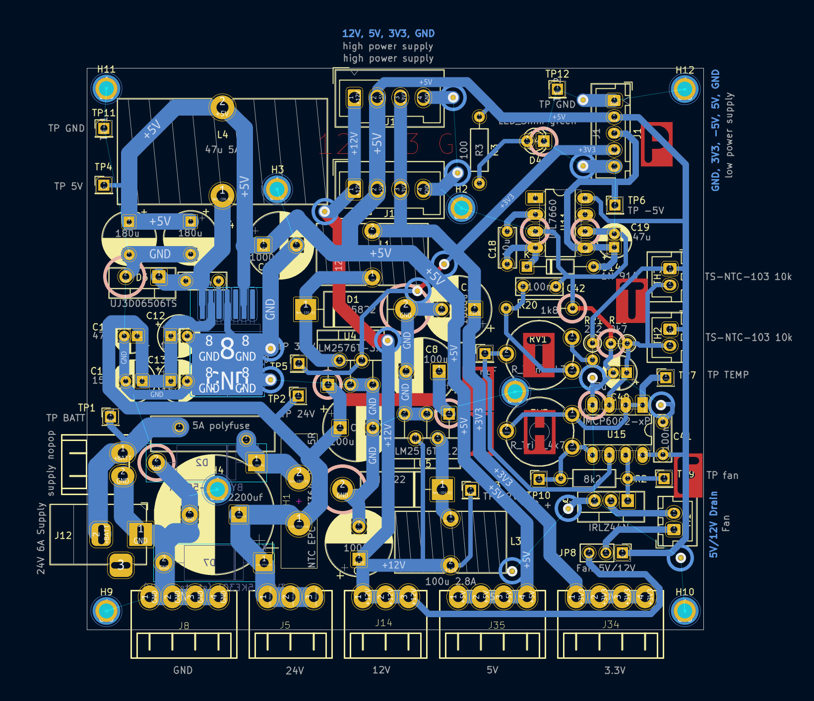
Creates different voltages from supplied 24 V. Supply for the Raspberry Pi interface board as well as several terminals for variable use (connect sensors, devices, etc., to the housing).
Photo
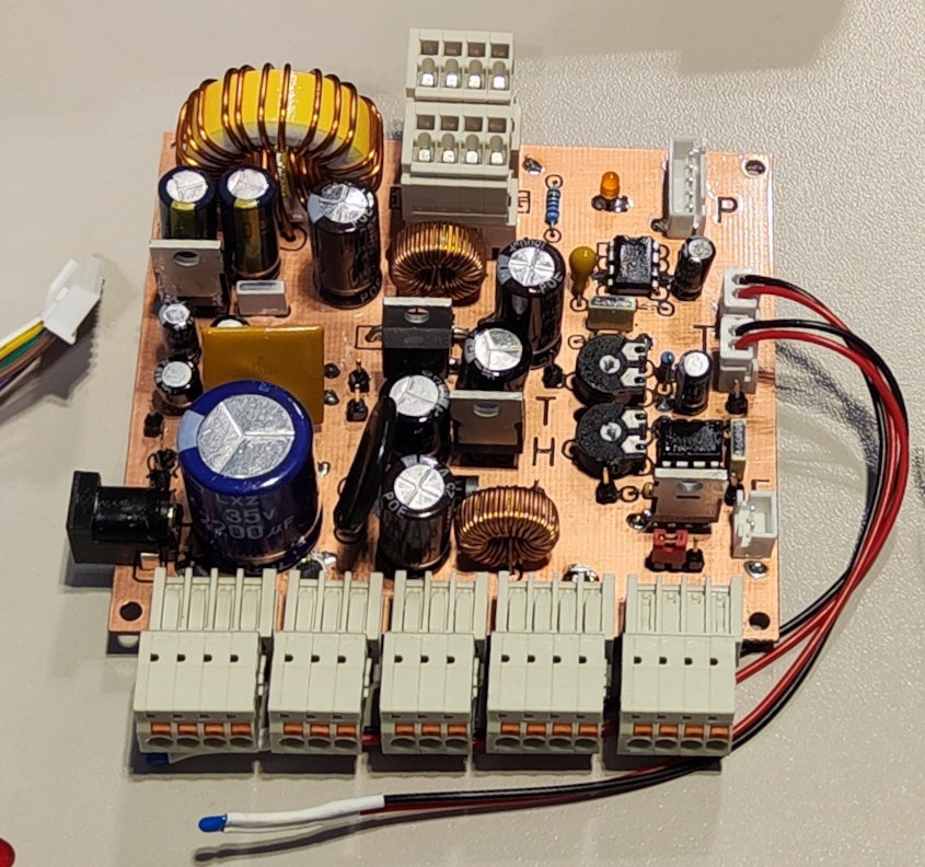
Features
Input:
- 24 V 5 A barrel plug.
- 5 A self-resetting polyfuse.
- Reverse polarity protection.
Output:
- 3.3 V, 3 A (buck converter).
- 5 V, 5 A (buck converter).
- -5 V, 20 mA (charge pump).
- 12 V, 3 A (buck converter).
- 24 V (supply voltage filtered).
Fan Control:
- 2x connector for 10 kΩ NTC.
- Threshold adjustable (trimmer potentiometer).
- Hysteresis adjustable (trimmer potentiometer).
- Select between 5 V or 12 V fan.
General:
- Spring-loaded terminals for each voltage.
- Combined internal terminals for all voltages.
Schematic and Layout
3. LED Boards
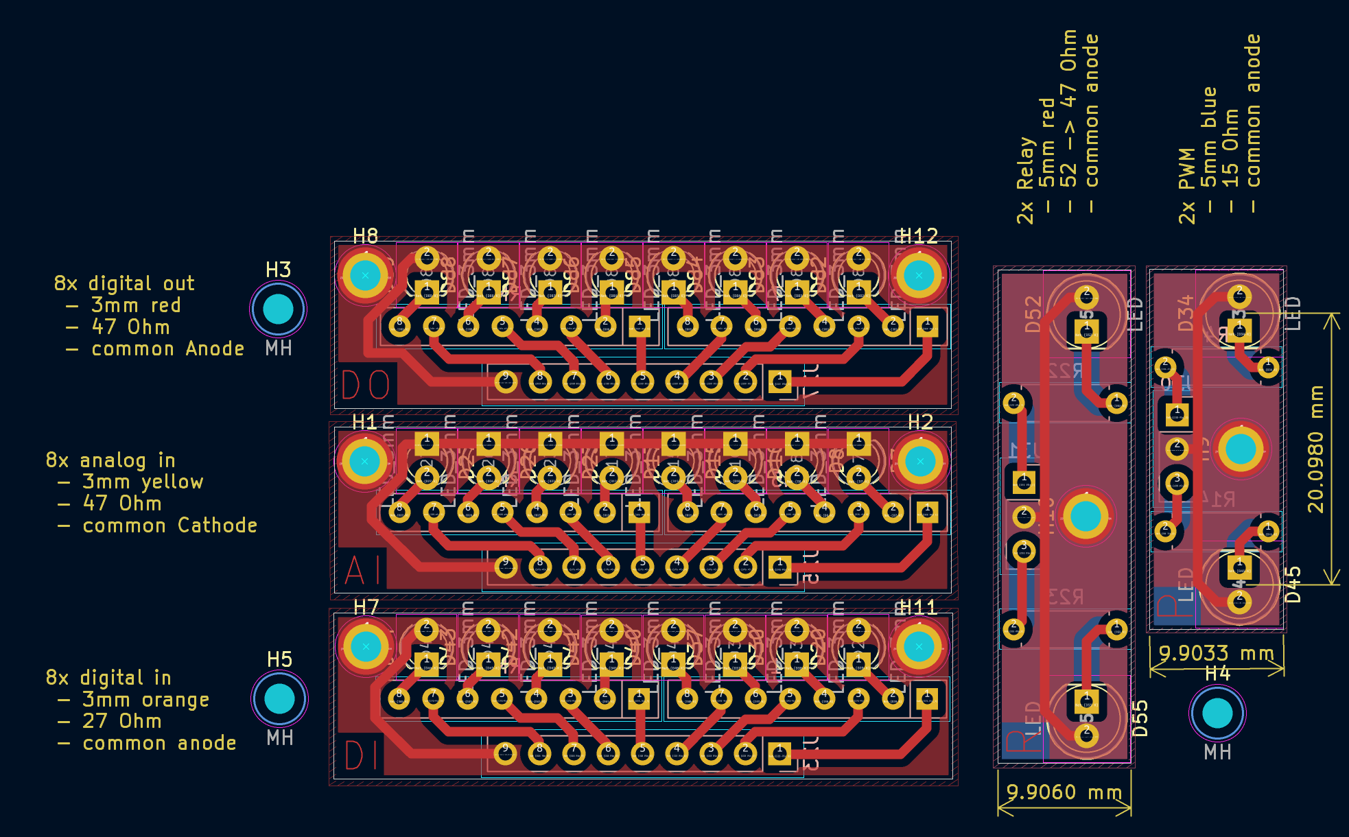
Small PCBs with LEDs, resistors, and mounting holes for housing indicators.
Photo
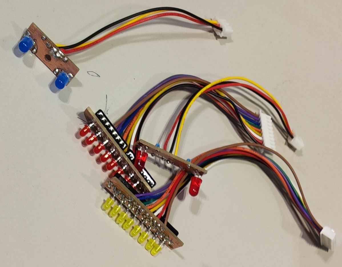
Boards
- 2x 5 mm LEDs for relays.
- 2x 5 mm LEDs for PWM outputs.
- 8x 3 mm yellow LEDs for analog inputs.
- 8x 3 mm orange LEDs for digital inputs.
- 8x 3 mm red LEDs for digital outputs.
Schematic and Layout
Software/Firmware
Python code for operating the extension PCBs (e.g., GPIO pins, shift registers, ADC, and bus communication). This section is a work in progress (WIP), and example scripts will be added as development continues.
======== WIP ========
Python scripting
The pin assignment to the actual terminals are defined / mapped in
rpi-scripts\interface_board_pins.py so it should be included in any custom script created to easily reference the terminal numbers printed onto the project housing in the code. See examples in rpi-scripts\examples
TODO: make those files link to file but with text still the file path
Usage Raspberry-PI
Connectivity
Establish LAN Connection (ethernet)
configure in command.txt in boot partition?
Establish WIFI Connection
s  nmcli device wifi connect <SSID> password <password>
# replace <SSID> and <password> with actual wifi
Connect via ssh
ssh pi@192.168.1.100
Connect via rdp
Open mstsc from windows start menu, and enter ip, user root and password. Or use powershell:
mstsc /v:192.168.1.100:3389
Note: currently only user root works (using user pi results in blackscreen)
Mount filesystem in windows
You can mount /home/pi folder in windows natively using samba
Run in powershell to mount it as network device X (replace ip with the current ip of rpi)
Find out ip with running ip a on the raspberry
net use X: \\192.168.1.100\pi /user:pi
Scripts
Autostart GUI
git/rpi-interface-board/rpi-scripts/gui% s cp gui-start.service /etc/systemd/system/
======== END WIP ========
Housing
Custom-designed enclosure includes:
- Ports for Raspberry Pi.
- Banana sockets for power outputs.
- Exposed screw terminals.
- Openings for buttons and LEDs.
- Mounts for all PCBs and wiring.
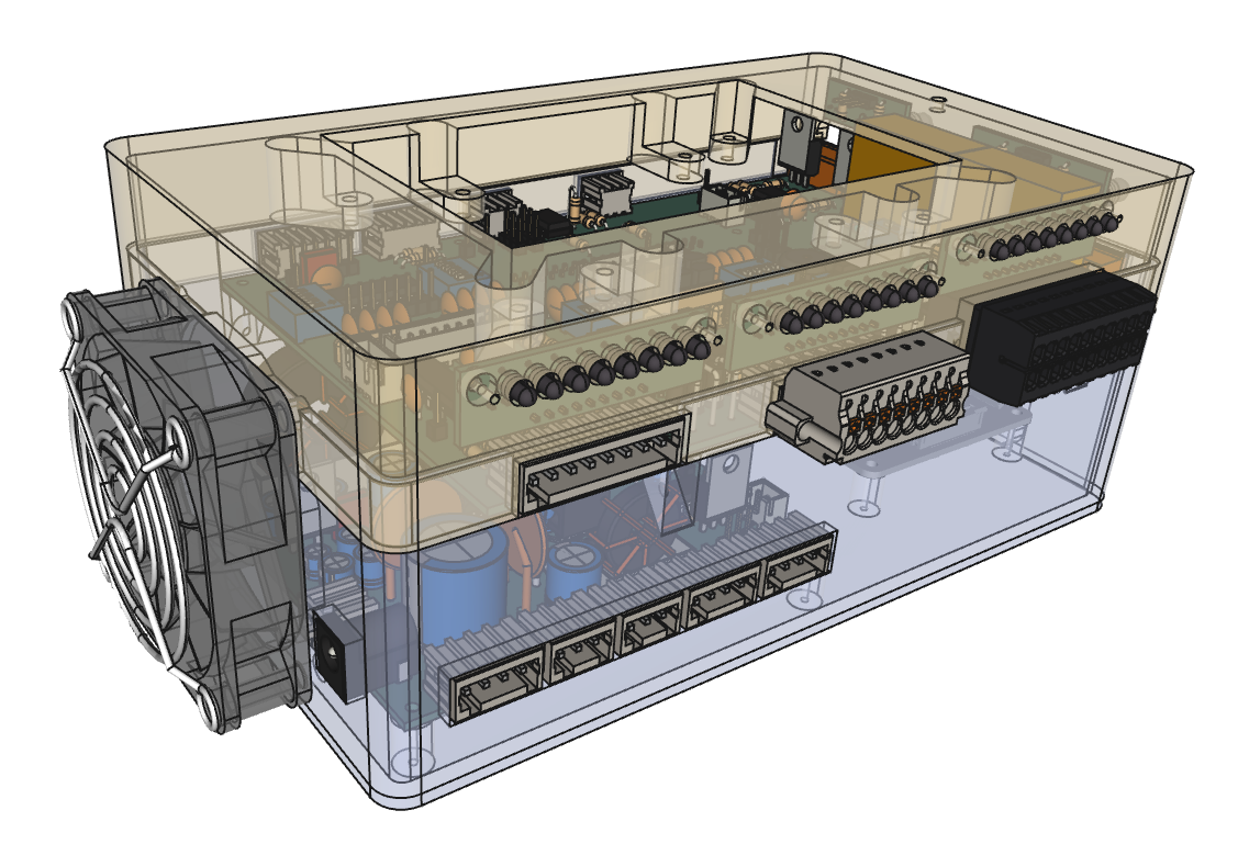
Dropped Features
The following ideas were considered but not implemented:
- UI Input Elements:
- Buttons, DIP switches, temperature sensors, encoders, or potentiometers.
- USB or battery-powered operation:
- Battery packs with BMS and voltage measurement.
- Li-ion cell holders.
- Analog output (DAC)
- More bus systems
- RS232 Interface
- CAN Interface
